
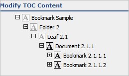
Example
The preview is similar to the following:

Modify Generated TOC
Make the changes to the generated TOC using the TOC editor.
Generated TOCs are created as Word documents and saved to the preview location specified in the TOC publishing settings for the assembly. These TOCs are complete except for the right column, which is generated during final publishing with cross-reference stamps and hyperlinks.
You can edit the TOC, including left column. You cannot edit the table and the right column links. These must be intact during final publishing, so they are stamped and linked appropriately.
Note: In some cases the TOC editor does not resolve a left column variable immediately. This happens if the left column variable is complex and requires additional processing to define. You may need to first generate the TOC to preview it.
Modify a Generated TOC
You can edit the TOC, including left column. You cannot edit the table and the right column links. These must be intact during final publishing, so they are stamped and linked appropriately.
To modify a generated TOC:
- In the assembly, click the TOC you want to edit.
- Verify the generated TOC file name and location.
- Access the document repository in the normal manner and edit the TOC.
Bookmarks
Bookmarks are taken directly from the source files, unless they have been modified or changed in the bookmark editor. In this case, the bookmarks are used for all TOCs and file output.
When the TOC is generated, either in the TOC editor or at publish time, Ennov InSight attempts to build a valid tree structure using the edited bookmarks or bookmarks extracted from source documents. If hierarchy levels are skipped or missed, Ennov InSight will 'compress' the bookmark tree in order to ensure valid published output.
During final TOC generation, two bookmark handling options are available: File Bookmarks and TOC Bookmarks.
File Bookmarks
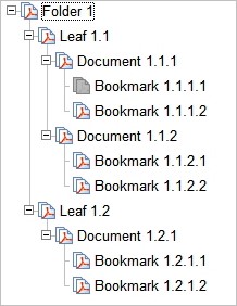
All final output files that span the range of a TOC contain their original bookmarks, and those bookmarks are used in the PDF output.
If multiple files are combined, they contain the bookmark trees of all source documents, plus a bookmark representing the document.
As shown in the example image, if you select File Bookmarks Only for all TOCs the final files contain the following (which is also the default for files that do not have tables of contents defined).

TOC Bookmarks
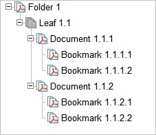
All final output files that span the range of the TOC contain the entire bookmark tree. For the output PDFs that fall within the range of that TOC, the bookmarks will match exactly what is shown in the generated TOC. Each TOC entry corresponds to a bookmark.
If multiple TOCs exist in this range and use this option, the TOCs are appended and the result is used as the bookmark tree. In the following example, if you select Use TOC Bookmarks for TOC #1 and TOC #2:
.jpg)
Use TOC bookmarks creates the following:

Use file bookmarks creates the following:
Leaf 1.1 file
Leaf 1.2 file
Leaf 2.1 file
Ennov InSight can generate bookmarks automatically for the output PDF file as part of TOC creation. The new bookmark text for each component document is determined from the left column text for the TOC element. With this function, the bookmarks for the final files can reflect exactly the content in the TOCs.
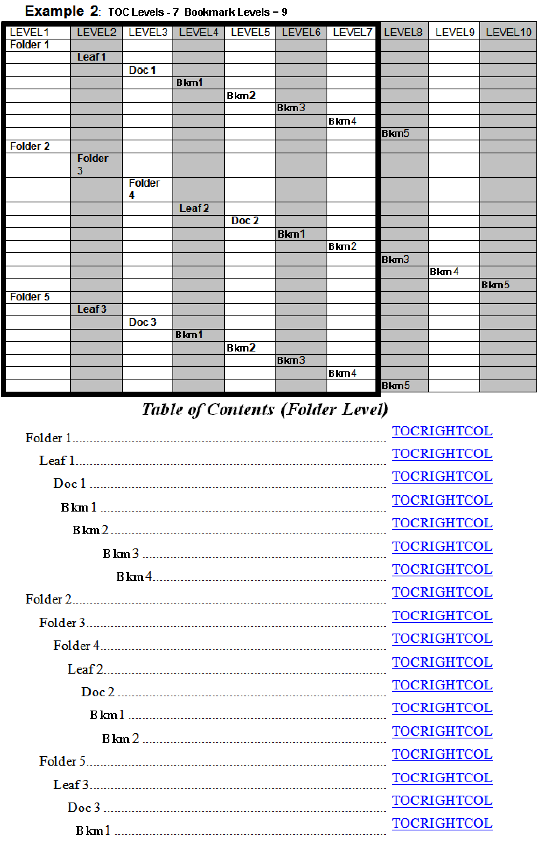
TOC Levels and Bookmark Levels
Bookmark levels are essentially a sub-setting of the TOC Levels setting. TOC levels defines how many levels will be displayed overall in the TOC and Bookmark levels determines how many levels of bookmarks are displayed within that number of TOC levels.
The following examples demonstrate the concept of TOC levels and Bookmark levels.
The first example shows how levels 3 and 4, although falling within the TOC level range, will not be included in the TOC because the number of levels of bookmarks to be included has been restricted to 2.
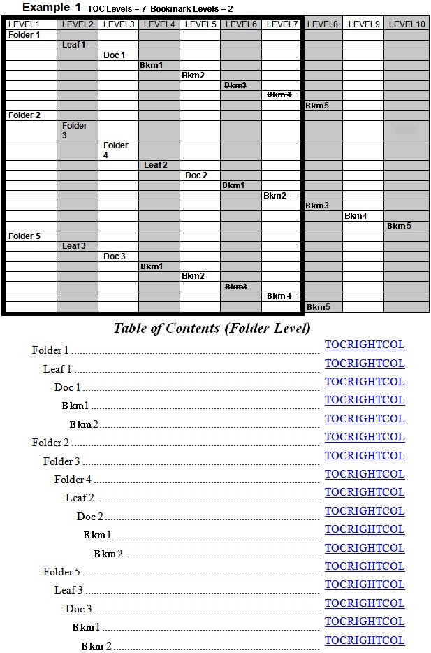
In the second example, Bookmarks at levels 8 and 9 in the assembly will not be included because TOC levels is restricted to 7.
In the third example, only one level of bookmarks will be included because the TOC level count starts from the invoked element.

TOC Entry Links
When a TOC entry is generated during final publishing, it is automatically hyperlinked to the page containing the TOC entry.
The destination is determined from the bookmark data that was used to create the TOC entry. The link area extends from the top left of the TOC link text column to the bottom right of the column. The link parameters are determined by the link publishing settings for the assembly.
Overlay Settings
With Ennov InSight , you can define headers and footers for certain elements in your assembly by creating and/or manipulating an overlay template file and specifying the overlay settings.
The overlay template is a file that you can create using Word. The overlay template can contain graphics, regular text, or variables that are resolved at publishing time. You can apply publication overlays to individual documents, cover pages, and TOCs. You can easily position graphics, text, or variables such as page numbers in the headers and footers of the document, and you can also specify font styles like you would in any other Word file.
You can create as many overlay files as needed. Ennov InSight enables you to define a default overlay file separately for each of the following types of elements in your assembly:
— All TOCs
— All cover pages
— All content documents
Ennov InSight can help you manipulate how overlay files are to be applied in multiple ways, including:
— Best fit - Used when working with overlay files that contain multiple pages. The multiple pages typically contain multiple page sizes (for example, A4 and US Letter) or multiple orientations (for example, portrait and landscape). Ennov InSight selects the best overlay page size and orientation to match the output page size and orientation after normalization.
— Rotation - Applied when there is a single orientation in an overlay file. You should choose to turn on overlay rotation when you have a portrait-oriented overlay that should be rotated to landscape orientation for landscapeoriented content documents. This results in all the headers and/or footers appearing at the same position on each page.
— Scaling - Enables you to indicate whether to scale the overlay to the output page.
When defining overlay publishing settings, many of the overlay values may already be populated, especially if you created your assembly by importing another assembly or template where overlay settings were applied. If this is the case, verify that your overlay settings meet the requirements for your new assembly.
Create or Modify Overlays
In the selected Publishing Settings Library, you can modify the Overlay Settings to adjust the default formatting of the overlay. This procedure applies to both the Publishing Settings Library Template (PLT) and Assembly Specific Publishing Settings Library (APL).
To modify the Overlay Settings:
- On the Publishing Settings Library window, select Overlays.
- Click Create
.png) .
.
To edit an existing overlay setting, click a named overlay in the list on the Overlays tab.
- On the Create/Edit Overlay Settings page, complete the required fields, and the optional fields as needed. Required information is indicated by an asterisk (*).
— Name *
— Overlay Template File (click Browse to locate and select the location)
— Default Overlay For (move items from the Available box to the Selected box to apply the Overlay settings by default for those items)
— Rotate Overlay to Content
— Apply Best Fit Overlay
— Scale Overlay to Content Page Size
— Scale Content to Margins
— Measurement Unit
— Portrait Margin Left
— Portrait Margin Right
— Portrait Margin Top
— Portrait Margin Bottom
— Landscape Margin Left
— Landscape Margin Right
— Landscape Margin Top — Landscape Margin Bottom
4. Save.
| Option | Action |
| To create another overlay setting, after saving the current settings: | Click Create Another Overlay. |
| To discard the changes: | Click Cancel. |
| To return to the Publishing Settings Library after editing an existing Overlay setting: |
Click the name of the Publishing Settings Library on the View page at the top of the page. |
Overlay Attributes
You can use the attributes to define the Overlay. Required information is indicated by an asterisk (*).
| Attribute | Description |
| Apply Best Fit Overlay | Choose Yes to apply the best fitting overlay page from the overlay template. Default is No. |
| Attribute | Description |
| Default Overlay For | Move publishing elements to the Selected box to specify this as the default overlay for the selected publishing elements. At least one overlay must be defined as the default for Cover Pages, Documents, and TOCs. Available options: Cover Pages, Documents, TOCs |
| Landscape Margin Bottom | The bottom margin on a landscape page. Enter a numeric value from .1 to 2 inches or .03 to 5.1 centimeters. |
| Landscape Margin Left | The left margin on a landscape page. Enter a numeric value from .1 to 2 inches or .03 to 5.1 centimeters. |
| Landscape Margin Right | The right margin on a landscape page. Enter a numeric value from .1 to 2 inches or .03 to 5.1 centimeters. |
| Landscape Margin Top | The top margin on a landscape page. Enter a numeric value from .1 to 2 inches or .03 to 5.1 centimeters. |
| Measurement Unit | Measurement used to indicate margin sizes. Available options: Inches, Centimeters. Default is Inches. |
| Name* | Specify the name of the overlay. Must be a unique name within the Publishing Settings Library. (Limit 100 bytes.) |
| Overlay Template File | Browse to select the template file stored in the document repository that will be used to generate the overlay. |
| Portrait Margin Bottom | The bottom margin on a portrait page. Enter a numeric value from .1 to 2 inches or .03 to 5.1 centimeters. |
| Portrait Margin Left | The left margin on a portrait page. Enter a numeric value from .1 to 2 inches or .03 to 5.1 centimeters. |
| Portrait Margin Right | The right margin on a portrait page. Enter a numeric value from .1 to 2 inches or .03 to 5.1 centimeters. |
| Portrait Margin Top | The top margin on a portrait page. Enter a numeric value from .1 to 2 inches or .03 to 5.1 centimeters. |
| Rotate Overlay to Content | Choose Yes to rotate the overlay to fit the content correctly. Default is No. |
| Scale Content to Margins | Choose Yes to scale the content to the margins defined for the overlay. Default is No. |
| Scale Overlay to Content Page Size | Choose Yes to scale the overlay to fit the content correctly. Default is No. |
Variables
You can set and modify variables at the publication level for headers, footers, tabs, cover pages, overlays, cross references, TOCs, and assembly elements. You can create variables, which may contain existing variables defined either at the assembly level or system-wide.
— Assembly level variables - These are normally user-defined variables used in the assembly for both electronic and paper publications. These variables are set up by an administrator in data administration and specified with the assembly or in the paper or electronic output templates for publishing. Publication variable settings specify which of these variables are scanned for or resolved for a particular publication.
— Data administration variables - These are used in the assembly for both electronic and paper publication. These variables are set up by an administrator and specified with the assembly or in the paper or electronic output templates. Publication variable settings specify which of these variables are scanned for/resolved for a particular publication.
Once defined, these variables can be used in two places:
— Assembly attributes and metadata - Variables are specified using their name and the delimiters described below. These variables are resolved during publishing and used within the eCTD XML metadata, tabs, TOCs, and volume names.
— Published output - Variables are specified using their name and the delimiters described below. These variables are resolved as,for example, page stamps on TOCs, special sheets, cross references, and overlays.
Delimiters
When creating a variable you should be aware of the how Ennov InSight accepts variables and delimiters. Ennov InSight uses the following types of delimiters:
— Dollar signs ($) and braces ({ }) are the delimiters used to describe how certain fields should be calculated in the system and/or resolved at publishing time. Always use these delimiters to describe, for example, how tab text should be resolved at publishing time. Dollar sign and braces delimiters are used in the assembly attributes and settings.
— Angle brackets (< >) are the delimiters used in Word to describe how the publishing engine should position variables in overlays and cover pages. You should always use these delimiters to insert variables that will be resolved directly as page stamps on overlays, cover pages, and other published output.
Create or Modify Variables
In the selected Publishing Settings Library, you can modify the variable settings. This procedure applies to both the Publishing Settings Library Template (PLT) and Assembly Specific Publishing Settings Library (APL).
- On the Publishing Settings Library window, select Variables.
- Click Create
.png) .
.
To edit an existing variable setting, click a named variable in the list on the Variables tab, and click Edit.
- On the Create Variable page, complete the required
fields, and the optional fields as needed. Required information is
indicated by an asterisk (*).
— Variable Code *
— Variable Name *
— Variable Value *
— Variable Type *
— Description
— Output Channel * (Move items from Output Channel Types to the Selected Output Channel Types box to apply the variable to the selected output channel types by default.)
- Save.
| Option | Action |
| To create another variable, after saving the current variable settings: | Click Create Another Variable. |
| To discard the changes: | Click Cancel. |
| If you are editing an existing Variable setting: |
Click the name of the Publishing Settings Library on the View page at the top of the page to return to the Publishing Settings Library. |
Delete a Publish Variable
You can delete a publishing variable at any level, as necessary.
To delete a publishing variable:
- On the Variables page select the variable you want to delete.
- Click Delete.
- Click Apply.
Variable Attributes
You can use the attributes to define the publishing variables. Required information is indicated by an asterisk (*).
| Attribute | Description |
| Description | Enter a description of the variable. (Limit 500 bytes) |
| Is Active* | Determines if the variable is active. Choose Yes or No. Default is Yes. |
| Output Channel* | Choose output channels to specify this as the default variable for the selected output channel types. Default is both, Electronic and Paper. |
| Variable Code* |
Specify the variable code that appears in the document or tree structure. The Variable Code and Output Channel combination must be unique within the Publishing Settings Library. The Variable Code must be different from any variable code defined in Assembly Repository Variables, Assembly System-Defined Variables, Assembly User-Defined Variables, or InSight Assembly Variables. (Limit 100 bytes.) |
| Variable Name* | Specify the human readable name of the variable. (Limit 100 bytes.) |
| Attribute | Description |
| Variable Value* | Specify the value to which the variable will resolve. This can be free text or another variable. (Limit 4000 bytes.) |
| Variable Type* | Choose the type of variable configuration. Available options: Single-Line Variable, Multi-Line Variable |
Link Profiles and the System Profile
Link profiles enable you to define how links are handled during publishing. These profiles can be created in a Publishing Settings Library Template (PLT), enabling you to create publications by starting with the saved profile values; you do not have to respecify the settings.
Ennov InSight provides you with a default profile called the System Profile.
— The System Profile is assigned automatically to all imported links.
— The System Profile is always used to create electronic TOC links and margin cross-references.
— Linking plug-in, in-process links and other inter-document links (links between documents) the System Profile is always applied to electronic and paper output, that is, the old links are deleted and the new links are applied.
— For intra-document links (links within a document) the assigned System Profile indicates that Ennov InSight does not alter these links during Electronic publishes unless it must. Any intra-document link formatting in the original documents is preserved in its original form, including style, font, color, and target settings. If a profile other than the default is used, or during a Paper publish, these settings are overwritten just like they are for interdocument links.
— When publishing to paper, the stamp generated for margin cross-reference links is created with the defined font type and font size.
Note: Not all formatting for old links can be deleted. For example, some underlines cannot be removed and text color cannot be changed. Also, intra-document links cannot be suppressed from published output. As a workaround, you can mask intra-document links by changing the link profile from the System profile to black text.
System Profile and Hyperlinks
If you use the System Profile, there are specific rules that Ennov InSight follows when publishing links. Ennov InSight writes out hyperlink settings and cross-reference stamp styles unless the link matches all of the following conditions:
— The link is an intra-document link (it points to another place in the document).
— The link is not published as part of a split document.
— The link has not been manually retargeted to another location.
The table of contents also always uses the System Profile for hyperlinks and the Table of Contents template for stamps. In all other situations, links that are set to the System Profile will always be written out exactly like the profile settings indicate. Also, when copying parts or an entire assembly to a new assembly, all link profiles are reverted to the System Profile.
When importing or copying assemblies from an assembly, all links are assigned automatically to the System Profile.
PLT Link Options
Link settings in a Publishing Settings Library Template (PLT) enable you to create hyperlink and margin crossreference styles at the publication level. These predefined settings are applied to your publication and establish how Ennov InSight formats links that were created during Publish time.
— The electronic hyperlink settings control the formatting of the hyperlinks that are published to the electronic output channel.
— The margin cross-reference settings control the formatting of the margin cross-references that will appear for output published to the paper output channel.
You can create, modify and view link settings (including color, size, and style) by clicking Links in the Publishing Settings dialog box.
Select a previously-created profile and links will use the settings defined in the profile. You can create a new profile by clicking Create Link Profile on the Link Profiles tab.
For paper publications, a margin cross-reference stamp appears in the margin next to text that contains a hyperlink.
The value used to format this margin cross-reference is based on the Margin Cross Reference Text Format field in the Link Profiles. You can create the variable name for the links in this field and enter any other data you would like to appear in the final publication.
Ennov InSight cannot remove underline styles from text when suppressing an existing hyperlink or cross-reference. Default Microsoft Word templates normally dictate that the link style is blue text, otherwise you will need to cleanup PDFs if they suppress, disable, or delete any hyperlinks or cross-references.
Links do not resolve correctly if they target a document page and the page in that document exists twice in the same assembly. Links work properly if the same document is assigned twice with two different page ranges for splitting up a document.
Create or Modify Link Profiles
This procedure applies to both the Publishing Settings Library Template (PLT) and Assembly Specific Publishing Settings Library (APL).
To modify the Link Profile settings:
- On the Publishing Settings Library window, select Link Profiles. The default Link Profiles appear.
- Click Create
.png) .
.
To edit an existing link profile setting, click a named link profile in the list on the Link Profiles tab.
- On the Create Link Profile page, complete the required
fields, and the optional fields as needed. Required information is
indicated by an asterisk (*).
— Link Profile Name* — Default?
— Electronic Hyperlink Style *
— Electronic Hyperlink Color
— Electronic Hyperlink Line Thickness (available when the selected Electronic Hyperlink Style is other than None)
— Margin Cross-Reference Size*
— Margin Cross-Reference Text Font Style
— Margin Cross-Reference Text Format
— Cross-Document Link Handling
- Save.
| Option | Action |
| To create another Link Profile, after saving the current Link Profile settings: | Click Create Another Link Profile. |
| To discard the changes: | Click Cancel. |
| If you are editing an existing Link Profile setting: |
Click the name of the Publishing Settings Library on the View page at the top of the page to return to the Publishing Settings Library. |
When you change the Default field for the link profile, it is important to remember:
— For a Link Profile with the Default value set to Yes: if you set the Default field to No and try to save the changes, an error message appears.
— If the Default value is set to Yes for a link profile, but you want to assign another link profile to be the default, set the Default field to Yes for the preferred link profile. The profile that was previously marked as default will be updated automatically.
Link Profiles Attributes
You can use the attributes to define the Link Profiles. Required information is indicated by an asterisk (*).
| Attribute | Description |
| Cross-Document Link Handling |
Determines if cross-document links are opened in the same window or in a new window. Available options: — Default — Open in the Same Window — Open in a New Window The Default option opens the cross-document link according to the Open Settings applied in Adobe Acrobat or Reader (Edit > Preferences > Documents). |
| Default? | Determines if this is the default link profile. The system automatically generates the default Link Profile (named System Profile). The default profile cannot be deleted. |
| Attribute | Description |
| Electronic Hyperlink Style* |
Choose the style of the hyperlink displayed in the published output. Available options: — Dashed Box — None — Solid Box — Underline |
| Electronic Hyperlink Color |
Choose the color of the hyperlink displayed in the published output. Default is Blue. Available options: — Blue — Black |
| Electronic Hyperlink Line Thickness | Defines the thickness of hyperlink line. This option is available when the selected Electronic Hyperlink Style is other than None |
| Link Profile Name* | Specify a name for the link profile. The name must be unique within the Publishing Settings Library. (Limit 100 bytes.) |
|
Margin Cross- Reference Size* |
Specify the font size to use for Margin Cross-References. Default is 10. |
|
Margin CrossReference Text Font Style |
Specify the font style to use for Margin Cross-References. Default is Arial. Available options: — Arial — Arial Narrow — Courier — Times New Roman — MS Mincho |
|
Margin CrossReference Text Format |
Specify the format to use for all Margin Cross-Reference links. Use variables. |
| Publishing Settings Library | The link to the Publishing Settings Library. |